


 简体中文
 Japanese
 Korean
 Russian
 繁体中文
 Español
Valve selection
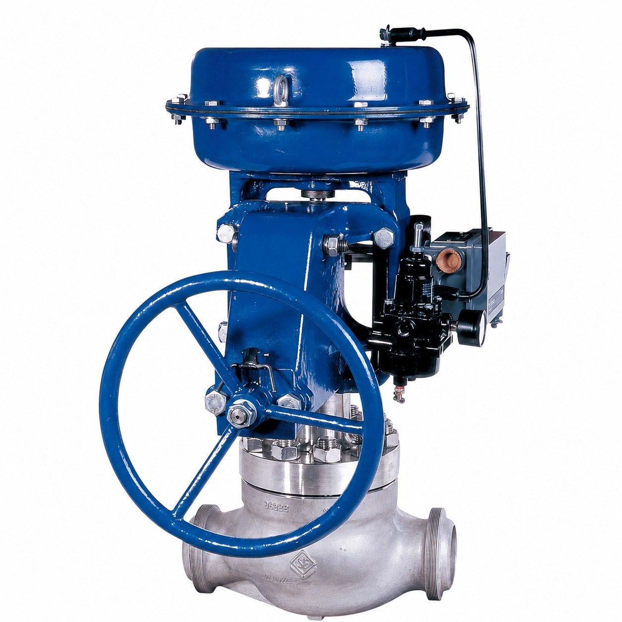
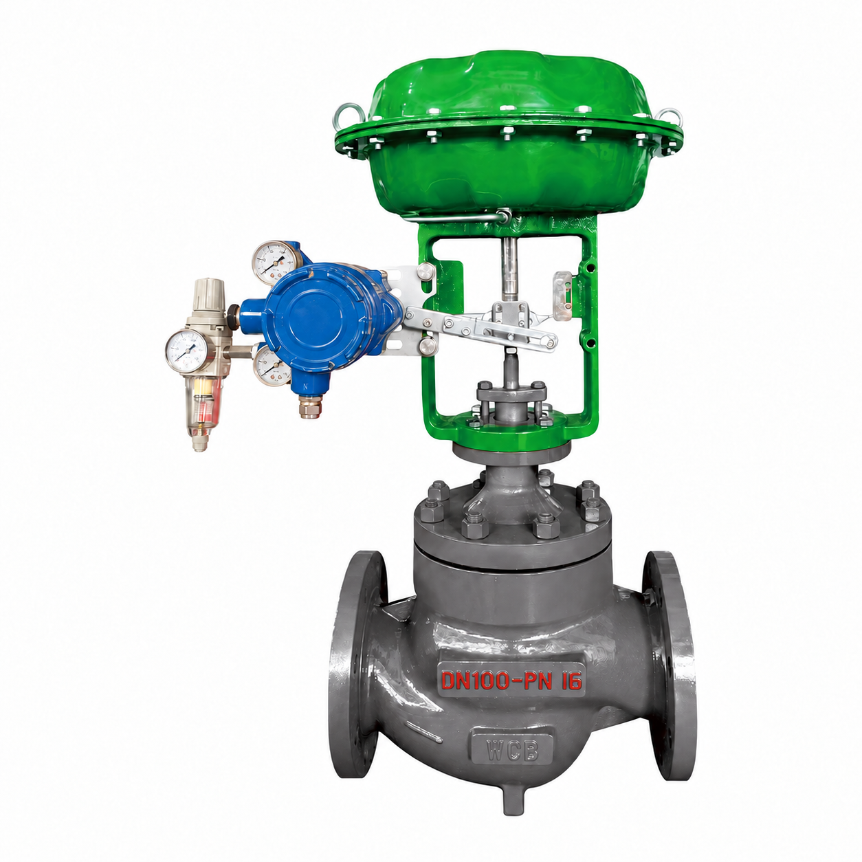
Cage type pneumatic control valve HCB-16C
Cage Pneumatic Control Valve HCB-16C Product Description
The HCB-16C cage type pneumatic control valve adopts a straight through cage type guiding structure, flange connection, and pneumatic diaphragm actuator, which is used for continuous control of industrial pipeline flow and related process variables. This model follows the configuration instructions for PN16 and WCB carbon steel valve bodies. Cage guidance helps to control the movement path of the valve core, and the actual adjustment performance needs to be determined based on the valve core structure, flow capacity, allowable pressure difference, and output capacity of the pneumatic actuator.
Product Specifications
| Product Model | HCB-16C |
| Structural form | Straight through cage guide, balanced valve core, flange connection |
| Nominal Diameter | DN20-DN300 |
| pressure rating | PN16 |
| Valve body material | WCB |
| sealing form | Metal seal or soft seal, choose according to leakage level |
| Drive Type | Multi spring thin film pneumatic actuator |
| Applicable temperature | -29℃ to 425℃, confirm according to valve internals and packing |
| Applicable Medium | Water, steam, gas, and clean process media |
Structure and working mode
HCB-16C adopts a straight cage guide, balanced valve core, and flange connection. The multi spring thin film pneumatic actuator converts air pressure into linear thrust of the valve stem, driving the valve core to move under the guidance of the cage sleeve, and adjusting the flow area. This two-way structure does not undertake the function of multi way reversing. The actuator should be selected based on the required valve stem thrust, stroke, working pressure difference, and instrument air source conditions; When continuous valve position control is required, the locator, control signal, valve position feedback, and safety requirements for gas on/off and gas loss should be checked.
Caliber pressure and material selection
The nominal pressure of this HCB-16C is PN16, and the valve body material is WCB cast carbon steel. It adopts a straight cage guide and balanced valve core structure. Metal seals or soft seals need to be selected separately based on the actual medium, design temperature, working pressure difference, and leakage requirements. Different sealing configurations cannot be treated as the same performance indicator. For steam, crystallization prone, particle containing, or frequent operating conditions, the valve core, seat, cage, packing, and possible abrasion should be checked. Other pressure and stainless steel material schemes should be determined separately based on their corresponding models.
Product features and applicable industries
The cage type guiding and balancing valve core structure of HCB-16C can be used for process regulation circuits that require control of valve core movement, flow rate, and pressure differential force. When used for steam pressure reduction and energy systems, the actual flow rate, upstream and downstream pressure, allowable pressure difference, and coordination between valve internals and actuators should be checked. The applicability of electrical accessories such as solenoid valves, positioners, and limit switches should be confirmed separately in hazardous areas. When it comes to food, high-purity, oxygen, corrosive or toxic media, corresponding material, cleaning and system safety conditions must also be met, and the applicability cannot be inferred solely based on the cage structure.
Installation and Debugging
Before installation, the valve nameplate, specified flow direction, flange standard, and structural dimensions should be checked, and welding slag and hard debris inside the pipe should be removed to prevent foreign objects from entering the cage and valve core activity area. The mating flange should be kept aligned and should not transmit pipeline stress to the valve body. Space for disassembly and assembly should be reserved around the pneumatic actuator, and the instrument air source should meet the requirements of the actuator and accessories. First debug and check the direction of gas opening and closing, valve stem stroke, locator or valve position feedback, safety position of gas loss, and interlock logic, and then perform corresponding sealing and action checks.
operation and maintenance
During operation, attention should be paid to the pressure and quality of the gas source, control signals, valve position feedback, abnormal noise, vibration, and external leakage. When there is a delay in movement, valve position deviation, or jamming, the air source processing accessories, locator, pneumatic diaphragm actuator, and valve stem movement should be checked, followed by checking the cage guide surface, balance structure, and valve core and seat status. Before maintenance, medium isolation, pressure relief, and residual energy release from the gas source should be completed; After replacing the components, check the valve stem stroke, sealing, and operating status according to regulations.
Q&A on Selection of Cage Pneumatic Control Valve
HCB-16C is used for larger pressure differentials, do we still need to choose specialized valve internals?
Need. Please provide the upstream and downstream pressure, medium temperature, and flow range to assess the risks of noise, cavitation, flash evaporation, and erosion. The name of sleeve or cage does not equal the already configured multi-stage pressure reducing or anti cavitation valve internals, and the specific plan should be confirmed according to the working conditions.
Do I need to confirm the input signal and valve position feedback when connecting HCB-16C to DCS?
It is necessary to confirm the control input, valve position feedback, power or gas source conditions, interfaces, and fault location separately. Input and feedback are not the same function, and it cannot be assumed that all analog signals or communication protocols are fully equipped based solely on the name "regulating type".
HCB-16C needs to be turned off after gas interruption. How should the actuator be configured?
The safety position required for the process in case of gas loss should be clarified first, and then the single or double acting scheme, output force or torque, and accessory circuit should be checked. You cannot select cylinders based solely on valve diameter, nor can you assume that all pneumatic configurations will close when there is a loss of air.
Order Information List
Suggest providing the name and composition of the medium, design and operating temperature, normal maximum and minimum flow rates, upstream and downstream pressures, maximum working pressure difference, flange standards, flow characteristics, allowable leakage requirements, instrument gas source, control signals, locator or feedback requirements, gas on/off form, and safe location for gas loss. Fouten Flow Control (Jiangsu) Co., Ltd. can be used to verify the cage valve internals, pneumatic actuators, and control accessory configurations of HCB-16C.
 Home
 Valve selection
 news information
 Contact us