


 简体中文
 Japanese
 Korean
 Russian
 繁体中文
 Español
Valve selection
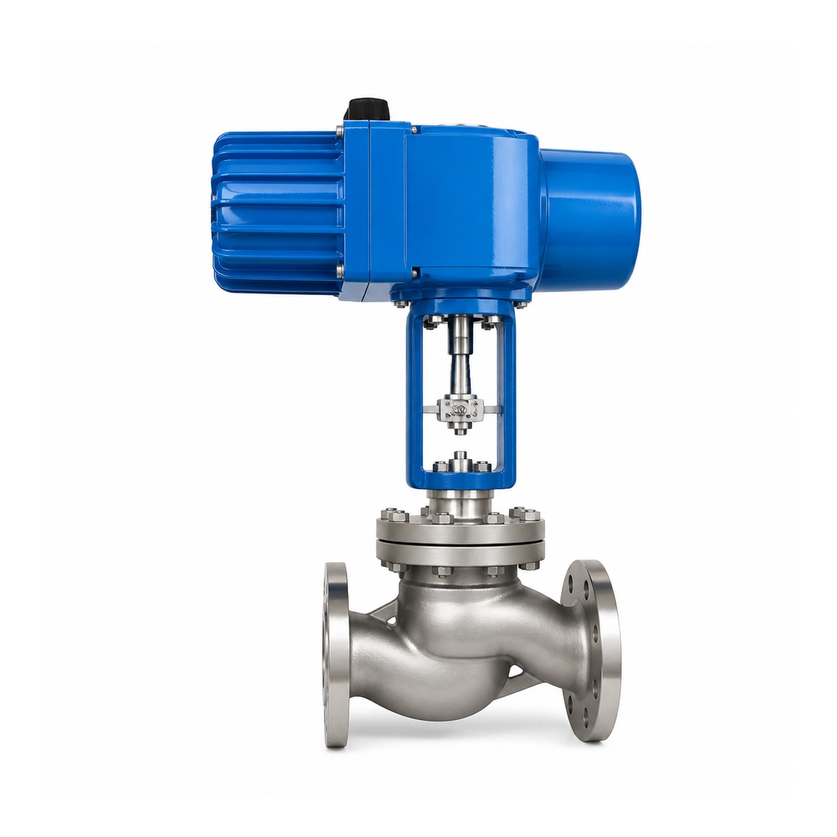
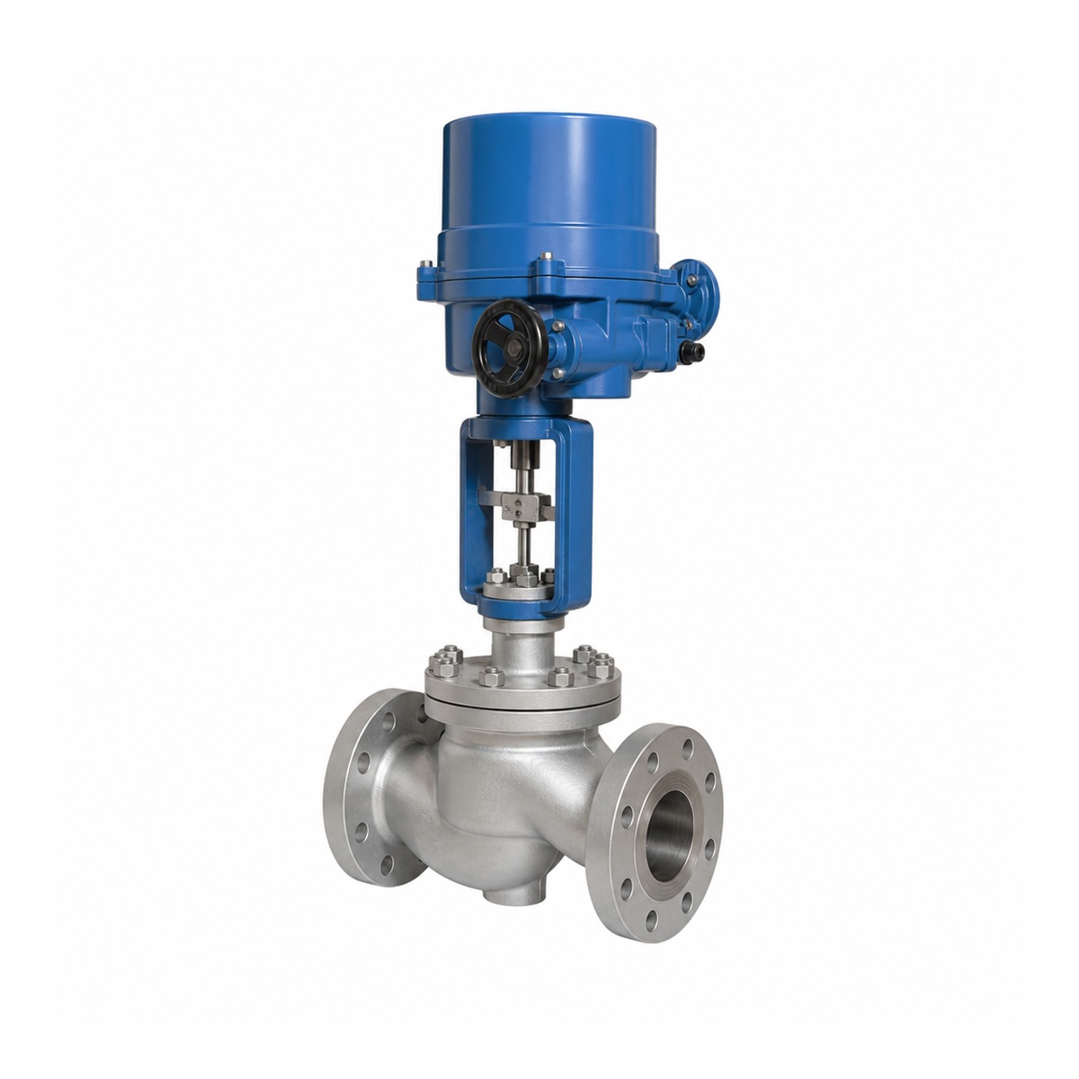
Electric single seat regulating valve ZAZP-25C
The ZAZP-25C electric single seat regulating valve adopts a straight through single seat valve body, flange connection, and a straight stroke electric actuator. The actuator drives the valve stem and valve core to move in a straight line, changing the flow cross-section between the valve core and valve seat, used for continuous throttling regulation of industrial pipelines. The nominal diameter series is DN15–DN400.
In the process control loop, measuring instruments provide flow, pressure, liquid level, or temperature signals, and the controller issues valve position commands based on target values. The regulating valve affects the controlled process by changing the flow rate. A single valve is responsible for regulating the circuit in which it is located, and is not a measuring instrument that independently controls all process variables at the same time.
Direct single seat structure and electric direct stroke drive
The straight through single seat structure is equipped with a main valve seat sealing channel inside the valve body, and the valve core moves along the axis of the valve stem to complete throttling through the gap between it and the valve seat. The valve body is responsible for pipeline connection and pressure load, the valve core and valve seat are responsible for throttling and closing, and the packing part controls the medium to leak outward along the valve stem.
The output of a linear electric actuator should be matched with the valve according to thrust and stroke. The fluid force inside the valve, packing friction, and sealing force required for closure all affect the driving demand; Valves with the same nominal diameter require different thrust forces under different closing pressure differentials and internal structures. The output torque of the angular actuator cannot be directly used as the required thrust for this valve stem.
The contour of the valve core affects the inherent flow characteristics. Linear and proportional characteristics describe the relationship between valve opening and flow capacity under specified conditions, and the actual flow after installation is also affected by pipeline resistance and pressure changes before and after the valve. When selecting valve internals, flow characteristics, rated flow coefficient, and primary operating opening should be considered together.
Control signals, valve position feedback, and failure actions
Power supply, valve position command, and position feedback are different interfaces. The power supply provides driving energy for the electric mechanism, inputs commands to give the target valve position, and reports the actual position detected through feedback signals. When using current signals, it is necessary to match the current input and range; When using voltage signals, it is necessary to match the voltage input and range, and wiring cannot be interchanged just because the values are similar.
4–20 mA belongs to current signals, 0–10 V belongs to voltage signals, and 0–10 mA is another current range. Different interfaces must be checked separately for input type, common terminal, range, and feedback method. Digital communication also requires corresponding hardware and protocol support, and it is not possible to infer that all communication functions have been configured from the name "electric regulating valve".
Continuous adjustment requires the actuator to be able to position according to valve position instructions and meet the actual adjustment frequency and load requirements. A switch type actuator with only fully open and fully closed actions cannot replace a complete continuous adjustment configuration. The stroke setting of the actuator should also correspond to the actual working stroke of the valve core to avoid inconsistency between the indicated position and the mechanical position.
Loss of control signal and loss of power supply should be evaluated separately. When there is still power supply, the control module can handle signal faults according to its actual function; After a complete power outage, the ability to continue to reach a safe location depends on the available energy storage or independent failure action structure. It cannot be assumed that a power outage will automatically shut down solely based on software settings, nor can valve position feedback be used as a substitute for sealing tests.
The comprehensive selection of driving mode, control interface, and on-site environment can be referred toSelection of electric valves and actuators。
Pressure, material and structural parameters
The nominal pressure range of this series is 1.6–6.4 MPa. The series range does not equal the allowable working pressure of a single ZAZP-25C at all temperatures, nor does it equal the maximum pressure difference that the actuator can close. The pressure bearing conditions of a single valve correspond to its nameplate, material, and pressure temperature rating. The closing pressure difference also needs to be matched with the valve core structure and actuator thrust.
The nominal pressure value and PN grade code should be written separately, and the PN prefix and MPa numerical unit cannot be combined into the same identifier. When matching with other flange systems, the flange hole spacing, sealing surface, structural length, and corresponding pressure and temperature conditions should also be checked, and approximate pressure values should not be used instead of checking the connection size.
The main material series includes WCB, WC6, stainless steel 304, and 316, with corresponding ordering conditions for different material configurations. The temperature limits of the valve body, valve core and seat, packing and actuator need to be evaluated separately, and the temperature resistance of a certain shell material cannot be directly used as the upper limit of the overall valve temperature. Corrosive media should also be checked for all contact materials, not just the valve body name.
| project | Structure and selection content |
|---|---|
| Product Model | ZAZP-25C |
| Valve body structure | Direct single seat |
| connection method | flange connection |
| Drive Type | Direct stroke electric actuator |
| Main actions | The valve stem drives the valve core to move in a straight line, continuously changing the throttling section |
| Nominal diameter series | DN15–DN400 |
| Series nominal pressure | 1.6–6.4 MPa; Not equivalent to the full temperature pressure bearing capacity or allowable closing pressure difference of a single valve |
| Main material series | WCB、WC6、 Stainless steel 304, 316 |
| Driver matching project | Thrust, effective travel, direction of action, frequency adjustment, and control interface |
| Capacity calculation input | Medium state, temperature, minimum normal maximum flow rate, and pre - and post valve pressure at each operating point |
Flow selection, installation, and debugging
The capacity of the regulating valve cannot be determined solely by the nominal diameter of the pipeline. It is necessary to calculate the required flow capacity based on the minimum, normal, and maximum operating flow rates and corresponding pressure differentials, and then match the valve internals and actuator. Choosing a valve that is too large can cause normal operation to be concentrated at a smaller opening, increasing the risk of unstable control; If the selection is too small, it may not be possible to achieve the target traffic.
The physical properties and flow conditions of water, steam, oil products, and industrial gases are different in capacity calculation. When there is a significant pressure drop in the liquid, it is also necessary to evaluate vaporization, cavitation, or flash evaporation; The compressibility and noise conditions should be considered for steam and gas operating conditions. The single seat structure itself cannot replace these calculations, nor can it guarantee that any high-pressure differential condition can be directly used.
Before installing the flange, the flow direction, pairing standards, and maintenance space should be clearly defined. When comparing single seat, sleeve, and other adjustment structures, reference can be madeStructure and Flow Selection of Industrial Control Valves。
- Before installation, clean the welding slag and debris inside the pipe, arrange the valves according to the flow direction of the valve body, check the flange alignment, gasket position, and pipeline support, and do not forcefully correct the pipeline misalignment with the valve body.
- Verify the power supply, protective grounding, and wiring terminals of the executing mechanism, distinguish between power lines, input signals, and feedback signals; Electrical wiring and inspection shall be carried out by personnel with corresponding qualifications.
- After meeting safety conditions, calibrate the stroke endpoint and valve position feedback, check the valve stem connection and action direction to avoid actuator overtravel or continuous overload at the mechanical endpoint.
- Gradually introduce control circuits from low-risk conditions, and check valve position tracking, flow rate changes, oscillations, and internal and external leaks under representative loads; The signal interruption and power-off tests shall be conducted separately according to the confirmed safety plan.
- Complete pipeline isolation, pressure relief, and residual medium treatment before maintenance, cut off and prevent accidental restoration of power supply; When involving energy storage mechanisms, safely release the energy storage simultaneously and do not disassemble it under pressure or in a state of possible accidental action.
Provide Fouten Flow Control (Jiangsu) Co., Ltd. with the medium, temperature, operating flow rate, pressure before and after the valve, connection size, and on-site control requirements, which can respectively determine the valve capacity, pressure bearing materials, actuator, and interface configuration. When explosion-proof is required, the hazardous area and corresponding certificate requirements should be clearly defined, and ordinary electric configurations cannot be directly used as explosion-proof configurations.
ZAZP-25C Electric Single Seat Regulating Valve Common Problems
Why do we need to check both stroke and thrust at the same time for ZAZP-25C?
The stroke determines the working position that the valve core can reach, while the thrust determines whether it can operate normally under fluid forces, packing friction, and sealing loads. The valve may still fail to adjust or close due to sufficient travel but insufficient thrust; Therefore, it is necessary to match the actuator with the actual closing pressure difference.
Can 4–20 mA input, 0–10 V input, and valve position feedback be mixed?
Cannot be directly mixed. Current input and voltage input require different interfaces and range settings, and input commands and output feedback also undertake different tasks. When wiring, the actuator terminals and control system interfaces should be matched one by one, and the feedback terminal should not be used as the instruction input terminal.
Does the series nominal pressure 1.6–6.4 MPa mean that each ZAZP-25C can be used according to 6.4 MPa?
No. The series includes different pressure configurations, and a single valve is still used according to its nameplate, material, and pressure temperature rating. This range is not allowed to close the pressure difference or adjust the pressure setting range, and cannot replace the technical conditions of a single valve with a series upper limit.
 Home
 Valve selection
 news information
 Contact us