


 简体中文
 Japanese
 Korean
 Russian
 繁体中文
 Español
Valve selection
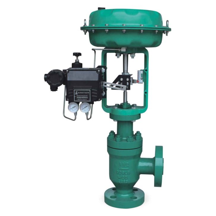
Pneumatic right angle flange connection regulating valve
Thin film pneumatic right angle flow control valve is an automated device used for fluid control in industrial pipeline systems, which achieves precise adjustment of medium flow rate through pneumatic signal drive. Its structural design combines the characteristics of a thin film actuator and a right angle valve body, making it suitable for working environments with limited space or the need to change fluid flow direction.
The core components of this valve include the valve body, valve seat, valve core, pneumatic actuator, and supporting accessories. The valve body adopts a right angle structure design, and the inlet and outlet channels form an angle of 90 degrees, which can effectively reduce fluid resistance and adapt to complex pipeline layout requirements. The mating surface between the valve core and valve seat is precision machined and can be treated with hard alloy, stainless steel, or special coatings according to the characteristics of different media to ensure sealing performance and service life. The thin film pneumatic actuator consists of an elastic diaphragm, a spring component, and a push rod. By receiving the standard gas source pressure signal from 0.2-1.0bar, the pneumatic energy is converted into mechanical displacement, driving the valve core to perform linear motion.
In terms of working principle, when the control system outputs a pressure signal, the actuator diaphragm deforms and pushes the push rod, driving the valve core to change the flow cross-sectional area. The stroke of the valve core corresponds linearly with the input air pressure, and with the help of a locator, it can achieve adjustment accuracy within ± 2%. The design of a right angle flow channel can reduce the impact of high-speed fluid on valve components and minimize the occurrence of cavitation. The valve body material can be selected from cast steel, stainless steel, or special alloys according to the characteristics of the medium. The working temperature range covers - 40℃ to 450℃, meeting the needs of different industrial scenarios.
The main technical characteristics of this type of valve are reflected in three aspects: firstly, it adopts modular design, and the actuator and valve body can be quickly separated for maintenance; Secondly, equipped with a manual operating mechanism for emergency adjustment in case of gas source failure; Thirdly, it is compatible with multiple control signal interfaces and can seamlessly integrate with automation systems such as DCS and PLC. In terms of application fields, it is commonly used in chemical production for reactor feed control, pressure balance regulation of petroleum pipelines, flow distribution of water treatment systems, and other scenarios, especially suitable for working conditions containing particulate matter or high viscosity media.
Product performance parameters usually include nominal diameter DN15-DN300, pressure rating PN16-PN100, and leakage rating that meets the ANSI/FCI 70-2 Class IV standard. During installation and maintenance, attention should be paid to maintaining the cleanliness of the gas source, regularly checking the elasticity of the diaphragm, and developing a maintenance cycle for the valve seat sealing surface based on the characteristics of the medium. Through reasonable selection and configuration, this type of valve can effectively improve the stability of industrial process control and energy utilization efficiency.
Common problems in product selection
Can TJ44W directly replace the existing straight through regulating valve?
The interface direction of the angle valve is different from that of the straight through valve, and the installation size, flow direction, flow coefficient, and allowable pressure difference should be checked; The proximity of the elbow positions on site does not necessarily mean that they can be directly replaced. It is also necessary to check the pipeline support and actuator maintenance space.
Do I need to confirm the input signal and valve position feedback when connecting TJ44W to DCS?
It is necessary to confirm the control input, valve position feedback, power or gas source conditions, interfaces, and fault location separately. Input and feedback are not the same function, and it cannot be assumed that all analog signals or communication protocols are fully equipped based solely on the name "regulating type".
TJ44W needs to be turned off after gas interruption. How should the actuator be configured?
The safety position required for the process in case of gas loss should be clarified first, and then the single or double acting scheme, output force or torque, and accessory circuit should be checked. You cannot select cylinders based solely on valve diameter, nor can you assume that all pneumatic configurations will close when there is a loss of air.
 Home
 Valve selection
 news information
 Contact us