


 简体中文
 Japanese
 Korean
 Russian
 繁体中文
 Español
Valve selection
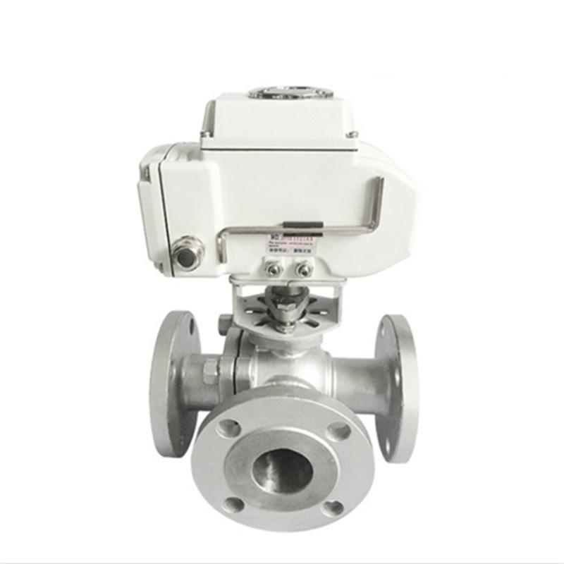
Electric four-way ball valve Q946F-16P
Electric four-way ball valve Q946F-16P
The Q946F-16P electric four-way ball valve changes the connections between four ports by rotating its ball into defined positions. It serves compatible circulation, bypass and process-routing duties. The electric actuator and flanged body bring these switching functions into one assembly.
Product Specifications
| Product Model | Q946F-16P |
| Structural form | Four way flow channel, flange connection, floating ball structure |
| Nominal Diameter | DN15-DN150 |
| pressure rating | PN16/PN25 |
| Valve body material | CF8/CF8M |
| sealing form | PTFE or enhanced PTFE soft seal |
| Drive Type | Angular stroke electric actuator |
| Applicable temperature | -20℃ to 180℃, confirm according to the sealing material |
| Applicable Medium | Water, oil, air, and compatible process media |
How the valve moves and seals
The drilled passages and actuator stops determine which ports communicate at each position. During movement, openings may overlap or close in a particular sequence. That sequence affects branch pressure and mixing, so control commands and feedback are assigned to the actual port arrangement.
Body and sealing materials
The CF8 or CF8M body carries pressure, while PTFE or reinforced-PTFE seats seal against the ball. The four branches may have different fluids, temperatures and pressures. Materials cover all intended operating and cleaning conditions, and actuator output covers the load throughout switching.
Operating conditions
For two groups of pipes that connect alternately, draw the port pairs at position A and position B, then consider whether flow interruption or temporary communication is acceptable. Large branch-pressure differences also affect reverse flow and pressure changes. Coordinate valve travel with pump and equipment sequencing.
Installation and commissioning
Identify and support all four connected pipes independently. Bring flanges into natural alignment and tighten evenly so the body does not carry pipe bending loads. Leave access to the actuator and, under safe isolation, verify each operating position, its real route and its feedback.
Inspection and maintenance
Unexpected pressure in one branch can result from changed pipe resistance, an incorrect stopping position or leakage through a closed route. Compare pressures and valve position at the same operating state. Before maintenance, isolate every port that can supply pressure and prevent unintended electric movement.
More electric ball valves are availableSelection of electric ball valveThe three-way reversing structure can be referred toQ945F-16P electric T three-way ball valveandQ944F-16P electric L three-way ball valve。
Q946F-16P Electric Four way Ball Valve Common Problems
How do we avoid connecting the four pipes incorrectly?
Number the ports using the ball-flow diagram and compare the connection table at every operating position. Commission the actual routes as well as the control display, including any required transition sequence.
Is a pressure jump during changeover always caused by fast actuator travel?
Travel time is one influence. Branch pressure differences, flow velocity and changing port overlap also affect the response. Compare pressure trends with the switching sequence before selecting travel time, buffering or interlocks.
What should we specify if the existing route must remain after a power failure?
State whether failure can occur at an end position or during travel, and which stopping positions are acceptable. Select the drive and control arrangement accordingly; completing a defined movement after power loss requires suitable stored energy.
Ordering information
Provide four numbered ports, a connection table for each position and the required separation during transitions. State each branch fluid, temperature, pressure and flow. Specify supply power, number of positions, feedback and failure response; replacements also need flange and overall dimensions.
 Home
 Valve selection
 news information
 Contact us