


 简体中文
 Japanese
 Korean
 Russian
 繁体中文
 Español
Valve selection
How to choose a fluoropolymer-lined regulating valve for corrosive media? Flow rate, pressure difference, and pneumatic electric configuration guide
The fluoropolymer-lined regulating valve first solves the compatibility of the medium, and also meets the requirements of flow rate, pressure difference, and control tasks. Separate the evaluation of corrosion, particle, and vaporization risks, and then select internal components, lining layers, and pneumatic or electric drives.
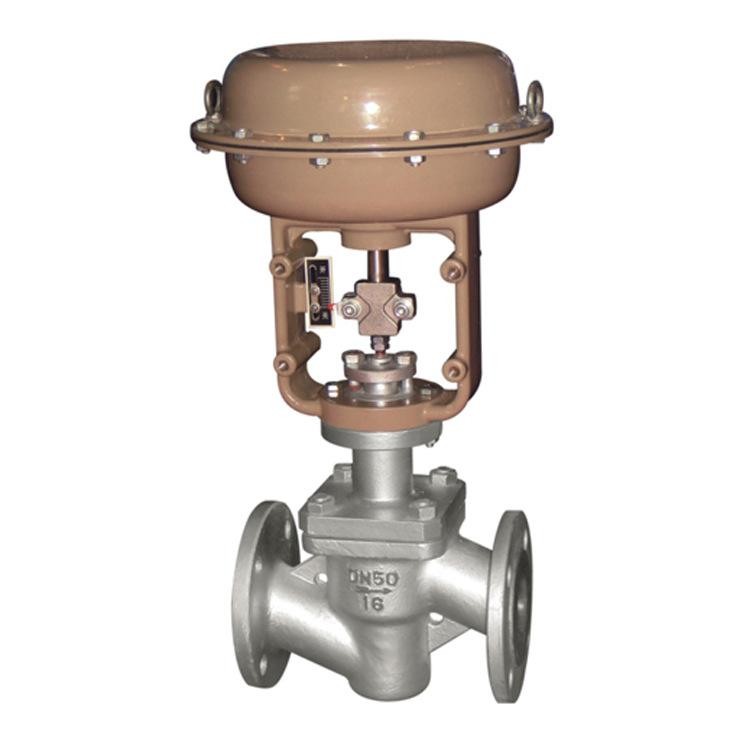
fluoropolymer-lined regulating valves typically adopt a structure that combines a metal pressure bearing valve body with a fluorinated polymer lining. By changing the position of the valve core through pneumatic or electric actuators, flow rate, pressure, or other process variables can be regulated.
Unlike ordinary cut-off type fluoropolymer-lined valves, fluoropolymer-lined regulating valves require simultaneous evaluation of material compatibility, flow coefficient, working pressure difference, valve internal structure, actuator output capacity, and actual control requirements.
The reasonable selection sequence for industrial pipelines involving corrosive fluids in chemical, environmental, pharmaceutical, and other industries should be:First, determine the medium and operating conditions, then calculate the flow capacity, and then select the valve internals, lining materials, and actuator.
1、 What is a fluoropolymer-lined regulating valve? What is the difference between ordinary fluoropolymer-lined valves?
fluoropolymer-lined regulating valve is a control valve that uses a fluorine-containing polymer lining and has an appropriate regulating structure at the valve's relevant liquid receiving parts.
The metal valve body is mainly responsible for pressure bearing and connection functions, and the lining is used to reduce the contact between corrosive media and the metal substrate.
The actuator drives the valve core to move according to the control signal, changes the valve flow area, and then participates in process control.
Ordinary fluoropolymer-lined ball valves, butterfly valves, and globe valves usually undertake opening, closing, or other specified control tasks according to their specific structures.
But for fluoropolymer-lined valves used for continuous regulation, they also need to have flow characteristics, stroke control capabilities, and valve internal structure that are suitable for the working conditions.
For example, even if a regular fluoropolymer-lined ball valve is equipped with an electric actuator that can stop at a certain intermediate opening, it cannot be considered suitable for long-term continuous fine adjustment based on this.
Similarly, a regulating valve with only PTFE valve seat or PTFE packing does not necessarily mean that the valve body flow channel adopts a complete fluoropolymer-lined structure.
The actual selection must specify which liquid receiving parts have lining, as well as the materials and structures of components such as valve cores and seats.
2、 Why can't fluoropolymer-lined regulating valves be selected based solely on pipeline diameter?
The main task of regulating valves is to change the flow capacity according to process control requirements.
Under the same pipeline diameter, different valve structures may have different rated flow coefficients.
Therefore, it is not enough to simply choose a fluoropolymer-lined regulating valve with the same nominal diameter based on whether the pipeline is DN50, DN80, or DN100.
Engineering calculations usually require the following working conditions to be provided simultaneously:
| Operating condition | Main data | Selection purpose |
|---|---|---|
| minimum flow | Minimum flow rate, corresponding pressure before and after the valve | Check low flow control capability |
| Normal traffic | Common flow rates, corresponding pressure differentials, and temperatures | Determine the main operating range |
| maximum flow | Maximum design flow rate and corresponding pressure | Check the maximum flow capacity |
| Maximum closing pressure difference | The maximum pressure difference that the valve may withstand when closed | Verify the closing force and actuator |
| abnormal condition | Temperature, pressure, and medium changes | Evaluate the boundaries of materials and valve internals |
The pressure difference may not be the same under different operating conditions.
If only the maximum flow rate is used to select the valve, it may cause the valve to remain in an inappropriate adjustment range for a long time during normal operation.
If only normal flow is considered, it may lead to insufficient flow capacity under maximum operating conditions.
When selecting a fluoropolymer-lined regulating valve, the required flow coefficient should be calculated based on the minimum, normal, and maximum operating conditions, and the actual adjustable range of the valve should be checked.
Regarding flow coefficient and flow characteristics, further reading is available Technical Guide for Regulating Valves Cv, Kv and Flow Characteristics。
3、 How should PFA, FEP, and PTFE liners be selected?
Common materials for fluoropolymer-lined valves include PTFE (F4), FEP (F46), and PFA.
All three materials belong to the fluorinated polymer system, but their processing methods, structural adaptability, and specific material properties are different.
| Lining material | Main Features | Attention should be paid when selecting |
|---|---|---|
| PTFE(F4) | Often using molding, sintering, machining, or specific forming methods | Lining structure, material grade, fixing method and working temperature |
| FEP(F46) | Can be processed by melting | Molding process, medium compatibility, temperature and pressure conditions |
| PFA | Can be processed by melting | Lining structure, material grade, medium compatibility, and working condition requirements |
When selecting materials, it is necessary to confirm the specific chemical composition of the medium, rather than just writing "acidic medium" or "strongly corrosive medium".
For example, there may be significant differences in the oxidation, concentration, and temperature conditions of different acidic substances.
The same material may also have different application boundaries under different medium concentrations, temperatures, or mechanical loads.
In addition, there is a throttling area inside the regulating valve, and local changes in flow rate and pressure difference may be more complex than normal cut-off conditions.
If the medium contains solid particles, is prone to crystallization, or has significant erosion, the wear resistance of the lining and valve internals should be evaluated simultaneously.
Chemical corrosion resistance does not equal mechanical wear resistance.
For the specific differences between PFA, FEP, and PTFE, please refer to Material selection for fluoropolymer-lined valves PFA, FEP (F46), and PTFE (F4)。
4、 What should be noted for high pressure differential working conditions of fluoropolymer-lined regulating valves?
The regulating valve forms a throttling effect through its internal components, and pressure loss occurs when the medium flows through the valve.
When the working pressure difference is large, the local flow velocity, pressure changes, and force inside the valve may increase significantly.
The following issues need to be given special consideration.
1. valve core and seat subjected to force
The working pressure difference may affect the movement and closing ability of the valve core.
The actuator must have sufficient output force to complete position adjustment or closing actions under specified operating conditions.
The thrust of the actuator cannot be determined solely based on the valve diameter.
2. cavitation risk
For liquid media, steam bubbles may be generated when the local pressure drops to near or below the vapor pressure at that temperature.
If downstream pressure is restored, bubbles may burst and cause mechanical impact.
Cavitation may affect valve internals, sealing areas, and service life.
3. Flash evaporation risk
When the liquid undergoes partial vaporization after passing through the valve and the downstream pressure is insufficient to allow it to re condense, flash evaporation may occur.
Flash evaporation conditions require special evaluation of flow rate, erosion, and valve channel structure.
4. lining mechanical stability
A larger local flow velocity and mechanical load may increase the workload of the lining and sealing structure.
The use of fluoropolymer-lined materials does not necessarily mean that the valve automatically has the ability to resist cavitation, flash evaporation, or special high-pressure differential control.
Therefore, the working conditions of high-pressure corrosive media should be specifically evaluated based on the properties of the medium, flow rate, steam pressure, actual pressure difference, and valve internal structure.
5、 What should be noted when using fluoropolymer-lined regulating valves for negative pressure conditions?
Some corrosive media systems may operate under vacuum, negative pressure, or alternating positive and negative pressure conditions simultaneously.
In this working condition, the fluoropolymer-lined regulating valve not only needs to check the pressure rating, but also needs to confirm whether the lining structure is suitable for the negative pressure state.
If the fixed structure of the lining does not meet the requirements of actual working conditions, local bulging, deformation, or other abnormalities may occur.
In addition, temperature cycling, medium infiltration, and lining forming methods may also affect actual usage.
Just because a product has PN16 or other positive pressure ratings, it cannot be considered suitable for continuous vacuum operation.
For pipelines involving vacuum or negative pressure, the minimum absolute pressure, temperature, and operating cycle should be specified.
For detailed instructions, please refer to Selection guide for vacuum negative pressure working conditions of fluoropolymer-lined valves。
6、 How to choose the actuator for pneumatic fluoropolymer-lined regulating valve?
The pneumatic fluoropolymer-lined regulating valve is driven by compressed air to operate the actuator, and can be equipped with a locator and related air source accessories according to control requirements.
For example, Fouten Pneumatic fluoropolymer-lined regulating valve HPF-16C The combination of pneumatic drive and fluoropolymer-lined regulating valve structure can be used as a product reference for flow control of corrosive media.
The actual project needs to further confirm the configuration of the valve body, lining, and valve internals according to the requirements of the medium, pressure difference, and flow rate.
When selecting a pneumatic fluoropolymer-lined regulating valve, it is important to focus on confirming:
- Normal, minimum, and maximum flow rates.
- Valve working pressure difference and maximum closing pressure difference.
- Pneumatic actuator outputs thrust.
- On site instrument air pressure and quality.
- Positioner and control signal.
- Gas on or off configuration.
- Safe location after loss of breath.
- Valve position feedback and interlocking requirements.
- On site protection and explosion-proof conditions.
For pipelines that require a fail safe location, it is necessary to clarify the expected actions when the gas source is interrupted, the solenoid valve loses power, and the control signal is abnormal.
The final safe position cannot be determined solely based on the "pneumatic thin film actuator" or "with locator".
The specific output capacity of the executing mechanism, lining material, allowable pressure difference, and leakage requirements should be based on the actual product data sheet and project technical agreement.
7、 What control requirements are suitable for electric fluoropolymer-lined regulating valves?
The electric fluoropolymer-lined regulating valve can be connected to the automation control system according to the actual control module configuration by changing the position of the valve core through an electric actuator.
The key selection criteria for electric drive solutions include:
- On site power supply conditions;
- The actuator outputs thrust or torque;
- Control input signal;
- Actual valve position feedback;
- Action frequency;
- Travel control and position protection;
- The processing method after losing control signals;
- Safety requirements after power failure;
- On site protection and explosion prevention requirements.
Partial adjustable electric actuators can be equipped with 4–20mA analog control and valve position feedback.
But whether it has these functions should depend on the specific execution mechanism and control module.
In addition, the loss of control signal and the loss of main power supply belong to different faults.
Some actuators can perform preset signal loss actions while there is still power, but it does not mean that they can still actively turn off or on after the main power is completely interrupted.
The selection of pneumatic or electric fluoropolymer-lined regulating valves should be comprehensively judged based on on-site energy, control tasks, operating frequency, maintenance conditions, and fault safety requirements.
8、 How to determine the requirements for sealing leakage of fluoropolymer-lined regulating valves?
The flow control performance and closing sealing performance of fluoropolymer-lined regulating valves belong to different technical requirements.
A regulating valve with good continuous adjustment capability does not automatically mean that it can achieve a specific level of tight cut-off.
The actual closing performance is also related to the valve core, valve seat, sealing material, closing force of the actuator, and test conditions.
If there are clear requirements for the closure of leaks in the project, they should be determined in the technical agreement:
- Applicable leakage levels and standards.
- Test medium.
- Test pressure difference.
- Allowable leakage amount.
- Valve core and seat materials.
- The ability to shut down the executing agency.
- Inspection and acceptance methods.
The actual leakage level cannot be judged solely based on words such as "PTFE soft seal", "fluorine lining", or "high sealing".
If the pipeline needs to be urgently cut off, it should also be clarified according to process safety requirements whether the same regulating valve can undertake this function or whether an independent cut-off valve is required.
9、 How to prepare inquiry parameters for fluoropolymer-lined regulating valves for corrosive media?
In order to reduce selection deviation caused by insufficient working condition information, it is recommended to provide the following data during the inquiry stage.
| parameter category | What needs to be provided |
|---|---|
| medium | Name, concentration, phase and corrosiveness |
| impurity | Particle, crystal, and sedimentation conditions |
| temperature | Normal, maximum, and minimum operating temperatures |
| Traffic | Minimum, normal, and maximum flow rates |
| pressure | Pre valve and post valve pressure under various flow conditions |
| Maximum closing pressure difference | Maximum design pressure difference in closed state |
| Nominal Diameter | Pipeline and valve connection dimensions |
| connection method | Flange standards and sealing surface forms |
| Lining material | PTFE, FEP, PFA or specified materials |
| trim | Valve core, valve seat and related liquid receiving components materials |
| Drive Type | Pneumatic or electric |
| Control requirements | Control signal, valve position feedback, and action frequency |
| Fault status | Requirements after loss of gas, power, and signal |
| Leakage requirements | Close the leakage level and acceptance conditions |
| Special working conditions | Vacuum, high pressure difference, cavitation, flash evaporation, etc |
After providing complete operating condition data, the valve flow coefficient, appropriate valve internal structure, lining material, and actuator combination can be further determined.
If there are hazardous chemical media or special safety requirements in the project, special confirmation is required in accordance with applicable engineering specifications and technical agreements.
10、 Practical steps for selecting fluoropolymer-lined regulating valves
The fluoropolymer-lined regulating valve can be selected for engineering in the following order.
Step 1: Determine the medium and material
Confirm the type, concentration, temperature, corrosiveness, and particle condition of the medium, and screen suitable lining and other liquid receiving component materials.
Step 2: Calculate traffic capacity
Provide minimum, normal, maximum flow rates and corresponding pressures, determine the required flow coefficient, and verify the actual adjustment range of the valve.
Step 3: Check the pressure difference and valve internals
Assess the maximum closing pressure difference, cavitation, flash evaporation, erosion, and the stress on the valve core.
Step 4: Select the executing agency
Determine the pneumatic or electric scheme based on the on-site gas source, power supply, and control method, and verify the thrust, stroke, and fault safety requirements.
Step 5: Clarify testing and acceptance
Determine lining materials, valve connection standards, control signals, leakage requirements, and related inspection items in the formal technical agreement.
More product structures can be referred to Special Topic on fluoropolymer-lined Valve Products。
Other regulating valve models and drive configurations can be entered Control Valve Product Center Comparison selection.
12、 Summary of Engineering Selection
The selection of fluoropolymer-lined regulating valves cannot be determined solely by material name, diameter, or driving form.
For corrosive medium pipelines, material compatibility should be confirmed first, then flow rate and pressure difference should be calculated, and then valve structure, valve internals, actuators, and control accessories should be determined.
For vacuum, high pressure difference, particle or other special working conditions, the actual applicable boundaries of the lining structure and valve should also be evaluated separately.
Fouten Flow Control (Jiangsu) Co., Ltd. provides selection services for industrial fluoropolymer-lined valves and pneumatic/electric control valves. The specific model, material, control configuration, and technical specifications shall be subject to the actual working conditions, confirmed product data sheets, and formal technical agreements.
Supplementary selection instructions
Can fluoropolymer-lined regulating valves be used for both continuous regulation and tight shut-off simultaneously? Confirmation is required based on the specific valve structure and technical requirements. Continuous adjustment performance does not equal a specific closing leakage performance. If both adjustment and tight cutting are required, the valve core and seat, actuator closing ability, test standards, and process safety requirements should be checked.
Common customer questions
Can fluoropolymer-lined regulating valves be used in strong acid media?
Partial fluoropolymer-lined regulating valves can be used for confirmed corrosive media, but the specific type, concentration, temperature, working pressure, and lining material of the acid must be specified. The scope of application cannot be judged solely based on "strong acid" or "corrosion resistance".
Is the larger the diameter of the fluoropolymer-lined regulating valve, the better the flow regulation effect?
No. The diameter of the regulating valve should be calculated based on the minimum, normal, and maximum flow rates, as well as the corresponding working pressure difference. The actual adjustment performance may be affected by the diameter being too large or too small, and cannot be selected separately according to the pipeline diameter or maximum flow rate.
Which is more suitable, pneumatic fluoropolymer-lined regulating valve or electric fluoropolymer-lined regulating valve?
It should be determined based on on-site energy, control requirements, output capability of the actuator, action frequency, and fault safety requirements. The pneumatic scheme requires reliable instrument air and air circuit accessories, while the electric scheme requires power and control interfaces that meet the requirements.
 Home
 Valve selection
 news information
 Contact us