


 简体中文
 Japanese
 Korean
 Russian
 繁体中文
 Español
Valve selection
How to configure the control and feedback of electric regulating valve 4–20mA? Actuator and debugging guide
The 4–20mA control command and valve position feedback are two different pieces of information. Please specify how to adjust and read back to the actual position separately in the inquiry, and then confirm that the electrical interface matches the system to avoid only connecting the control without effective feedback.
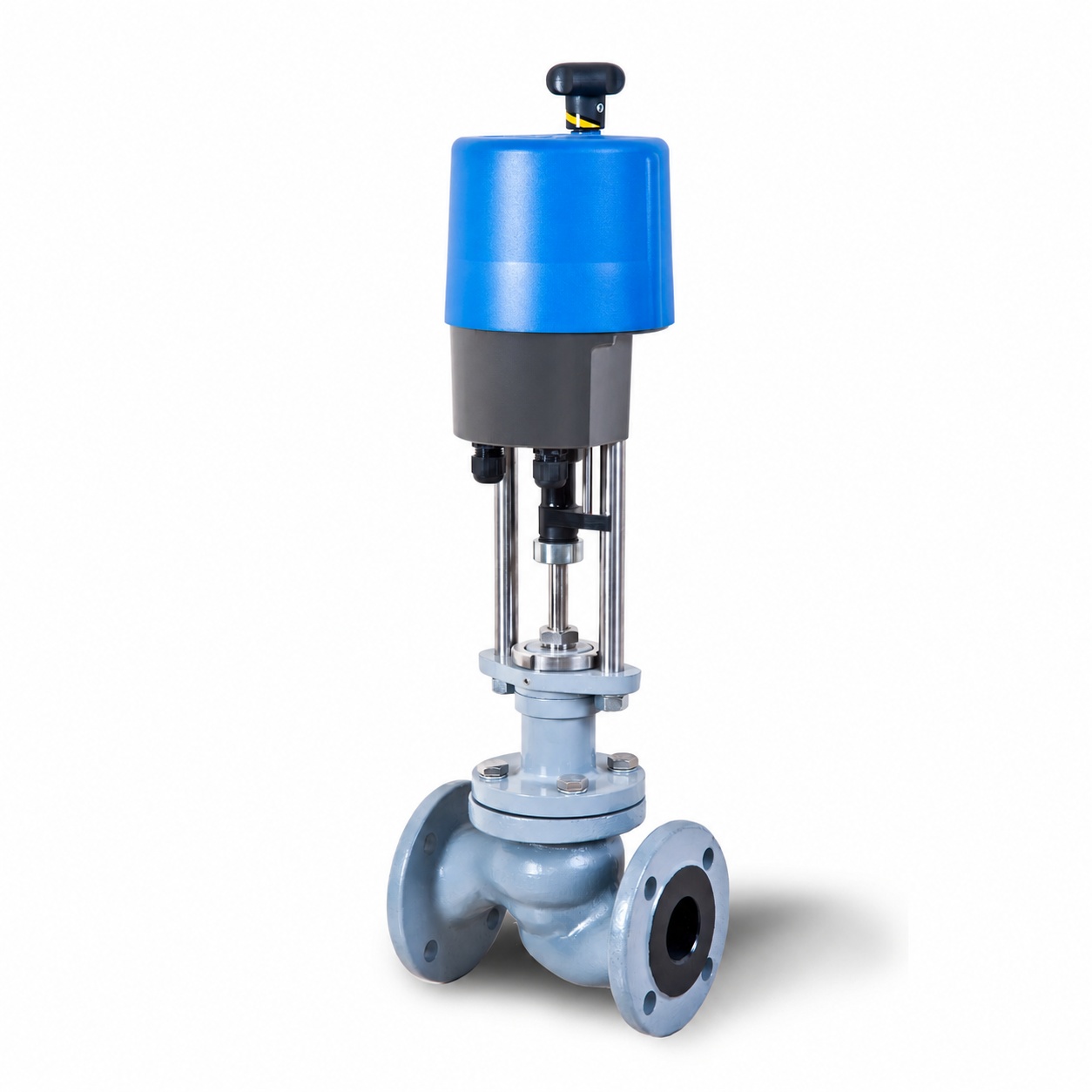
In practical engineering, the selection of valve body and electrical control configuration for electric control valves are equally important.
For example, even if the mechanical structure of an electric regulating valve meets the requirements of the medium and pressure, if the control signal type does not match, the actuator stroke setting is incorrect, or the valve position feedback is inconsistent with the control system configuration, it may not be able to complete the expected automatic adjustment task.
Therefore, when purchasing and debugging electric control valves, it is necessary to clearly distinguish between control signals, actual valve position feedback, switch in place signals, and fault states.
1、 What does electric control valve 4–20mA mean?
4–20mA is a common analog current signal in the field of industrial automation.
For electric control valves with corresponding analog control modules, the control system can send target valve position commands to the actuator through the 4–20mA signal.
For example, a certain electric actuator adopts forward linear stroke mapping and sets 4mA to correspond to 0% target stroke, and 20mA to correspond to 100% target stroke.
At this point, different control signals can correspond to different target positions.
| Analog control signal | Example target itinerary |
|---|---|
| 4mA | 0% |
| 8mA | 25% |
| 12mA | 50% |
| 16mA | 75% |
| 20mA | 100% |
The above is only an example of forward linear control and not a fixed setting for all electric control valves.
In practical engineering, the actuator may adopt reverse action, different stroke endpoints, or other specific control logic.
Therefore, 4mA does not necessarily mean that the valve is fully closed, and 20mA does not necessarily mean that the valve is fully open.
The correspondence between control signals and target positions should be based on the parameter settings of the actuator and the actual stroke calibration results.
2、 What is the difference between the control signal of an electric regulating valve and valve position feedback?
Control signals and valve position feedback are two different concepts.
control signal
Indicate the target position that the control system requires the valve to reach.
Valve position feedback
Indicate the actual valve position measured and fed back by the on-site executing agency.
For example, the control system requires the electric control valve to achieve the target opening of 60%, but due to abnormal stem resistance, mechanical jamming, or insufficient output capacity of the actuator, the valve actually only reaches the stroke position of 45%.
If the control system only has control outputs without actual valve position feedback, it may not be possible to directly detect this position deviation.
A control system with feedback function can compare the target valve position with the actual valve position to further determine whether the actuator is responding correctly.
It should be noted that valve position feedback usually reflects the valve stem stroke, actuator angle, or corresponding position detection results, and does not directly represent the medium flow rate through the valve.
Why do target valve positions and actual valve positions need to be monitored separately?
Because the control command has already been sent, it does not necessarily mean that the valve has completed the corresponding mechanical action.
Possible factors that may affect the actual location include:
- The output thrust of the actuator is insufficient.
- Abnormal resistance of valve stem or mechanical transmission mechanism.
- The travel limit setting is incorrect.
- The position detection device is abnormal.
- Control signal range configuration error.
- The actuator enters a fault or protection state.
- Valves are affected by abnormal pressure differentials or other operating conditions.
When the target valve position is continuously inconsistent with the actual valve position, it should be checked in conjunction with on-site alarms, actuator status, and control circuit data.
3、 Can 4–20mA input and 4–20mA feedback share the same signal line?
Just because both use 4–20mA, it cannot be assumed that they can share the same analog signal circuit.
The control input and valve position feedback of electric regulating valves belong to different functions.
The control system usually sends control instructions to the actuator through the analog output channel, and then receives valve position feedback from the actuator through the corresponding analog input channel.
The specific wiring method depends on the input and output modules of the actuator and the interface form of PLC or DCS.
For example, some analog interfaces require external circuit power supply, while others have different active or passive requirements.
If different types of analog interfaces are directly connected without verification, it may cause signal abnormalities or equipment damage.
Therefore, before formal wiring, it is necessary to confirm:
- Is the control module a current input or a voltage input;
- Does the actuator have an independent valve position feedback output;
- Electrical types of analog input and output interfaces;
- Requirements for circuit power supply and isolation;
- The positive and negative effects of control signals;
- Electrical grounding, shielding, and on-site wiring requirements.
Specific wiring terminals should not be directly determined based solely on "support for 4–20mA".
4、 What is the difference between electric control valve switch type and regulating type?
The switch type electric valve is mainly used for opening and closing tasks.
Adjustable electric valves require changing the actual position of the valve according to continuous control commands.
| comparison items | Switch type electric valve | Adjustable electric valve |
|---|---|---|
| main task | Turn on and off | Continuous valve position adjustment |
| Control method | Commonly referred to as switch quantity | Analog quantity and other methods can be used |
| position control | Mainly for endpoint control | Support target positioning within the prescribed scope |
| Feedback requirements | Commonly open and close in place | Configurable continuous valve position feedback |
| Selection of execution mechanism | Pay attention to opening and closing ability and action time | Positioning, action frequency, and control performance also need to be considered |
| Valve body requirements | Suitable for opening and closing tasks | It also needs to have a suitable adjustment structure |
It should be noted that having a 4–20mA control interface does not mean that any valve body is suitable for long-term continuous adjustment.
For example, even if a regular switch type ball valve can stay in a certain middle position, it cannot be directly equivalent to a professional regulating valve.
The adjustment capability depends on the valve core, valve seat, flow characteristics, actuator, and actual operating conditions.
5、 Why is the valve opening of 50% not equal to the flow rate of 50%?
This is a common issue in the selection and control of electric regulating valves.
The valve position percentage describes the position of the valve or actuator.
The flow percentage describes the actual fluid flow through a pipeline or valve.
There is no unified one-to-one correspondence between the two.
The main reasons include the following aspects.
The 1. valve itself has different flow characteristics
Common inherent flow characteristics include linearity, equal percentage, and fast opening.
Different valve core structures have different flow capacities at the same stroke position.
The actual pressure difference of 2. valve will vary with the working conditions
In real pipeline systems, changes in valve opening may also result in changes in system flow and pressure losses in various parts.
Therefore, the relationship between actual flow rate and valve opening may differ from the inherent flow characteristics of the valve under specified test conditions.
3. has different dielectric properties
The flow conditions of liquids, gases, and vapors are different, and there are also differences in calculation methods.
Some liquids also need to consider the risk of cavitation or flash evaporation.
Therefore, when the control system displays the valve position of 50%, it cannot directly infer that the actual flow rate is also the maximum flow rate of 50%.
For specific instructions on flow coefficient and flow characteristics, please refer to Selection Guide for Regulating Valves Cv, Kv and Flow Characteristics。
6、 How to match the actuator of electric single seat regulating valve and electric sleeve regulating valve?
Different valve body structures have different requirements for the output capability and control configuration of the actuator.
1. electric single seat regulating valve
Electric single seat regulating valves usually adopt a straight stroke structure, which is driven by an electric actuator to adjust the position of the valve stem and valve core.
For example, Fouten ZDLP-16C electric single seat regulating valve Can be used as a product reference for straight stroke electric control valves.
When selecting this type of product, it is necessary to verify:
- Valve diameter;
- Differential working pressure before and after the valve;
- Valve core and seat structure;
- Output thrust of actuator;
- Actual stroke of valve stem;
- Close leakage requirements;
- Control signals and valve position feedback;
- Power supply and troubleshooting methods.
The above conditions should be confirmed based on the actual model and operating conditions, and cannot be directly applied to the parameters of the unified actuator.
2. electric sleeve regulating valve
Sleeve regulating valves usually use sleeve guide or corresponding balance structures, and the actual regulating performance depends on the design of the valve internals.
For example, Fouten ZDLM-16C electric sleeve regulating valve Can be used to understand the structure of electric sleeve adjustment.
When determining the actuator, in addition to the normal adjustment requirements, it is also necessary to check the output capacity based on the maximum pressure difference, valve internal component stress, actual stroke, and leakage requirements.
The sleeve structure may improve the stress and motion stability under certain operating conditions, but it cannot be simply assumed that all sleeve regulating valves are suitable for any high-pressure differential operating condition.
3. actuator cannot be selected solely based on nominal diameter
Even if the nominal diameter of two valves is the same, different actuator output capabilities may be required due to differences in valve core structure, sealing form, medium pressure difference, and actual load.
Therefore, the electric actuator model cannot be directly determined based solely on the diameter of DN50 or DN100.
7、 What is the difference between signal loss and power loss in an electric control valve?
Loss of control signal
When the signal between the controller and the actuator is interrupted, the main power supply of the actuator may still be normal.
At this point, the actuator with corresponding control functions may maintain the current valve position, turn to a target position, or issue a fault alarm based on preset parameters.
The specific behavior depends on the model of the executing mechanism and the configuration of the control module.
Loss of main power supply
If the main power supply of the electric actuator is interrupted, ordinary electric drive devices usually cannot complete normal operations through the motor.
Only by configuring backup power supply, energy storage devices or dedicated fault safety mechanisms that meet the requirements can corresponding power-off actions be implemented according to the design.
Therefore, supporting signal loss shutdown does not mean supporting automatic power-off shutdown.
For processes that require a designated safe location after a malfunction, relevant requirements should be clearly defined during the ordering phase, and on-site temporary changes in control logic should not be relied upon to replace necessary safety designs.
8、 How to troubleshoot abnormal feedback of electric control valve position?
In actual operation, there may be situations where the given value of the control system is normal, but the valve position feedback is abnormal.
It can be distinguished based on the symptoms of the malfunction.
| Fault Symptom | Priority checked items |
|---|---|
| There is a control command, but the valve does not operate | Power supply, control mode, actuator alarm, and mechanical status |
| The direction of valve action is opposite | Positive and negative effects, wiring, and travel mapping |
| The valve is moving normally but there is no feedback | Feedback module, interface, and loop status |
| The feedback value is inconsistent with the actual travel | Travel calibration, feedback range, and position detection |
| Continuous deviation between target valve position and actual valve position | Output capability, resistance, control parameters, and limits |
| Frequent small movements of the valve | Control circuit tuning, signal fluctuation, and dead zone setting |
For feedback anomalies, it is necessary to first clarify whether it is a control signal anomaly, position feedback anomaly, or mechanical action anomaly.
If the site is in a hazardous environment, electrical and mechanical inspections must comply with equipment isolation, power outages, and site safety management requirements.
Limit and actuator mechanical components should not be directly adjusted when the equipment contains hazardous media or is in an unsafe state.
9、 What needs to be checked for on-site debugging of electric control valves?
The debugging of electric control valves needs to be carried out in conjunction with the instruction manual of the actuator, the design documents of the control system, and the process requirements.
1. confirms power supply and electrical interfaces
Check the power type, voltage, grounding requirements, and control signal interface to confirm consistency with the actual actuator configuration.
2. confirms mechanical travel
Check whether the allowable stroke of the valve matches the setting of the actuator to avoid exceeding the mechanical limit of the valve.
3. confirms control direction
Check whether the control signal changes are consistent with the direction of valve action according to the approved debugging program.
4. Verify Travel Feedback
Verify the actual valve stem position and feedback signal at the designated testing location, and confirm that the range and endpoint settings are reasonable.
5. inspection limit and protection function
Confirm that the functions such as travel limit, output capacity limit, and fault alarm meet the requirements of the executing mechanism and project.
6. check signal loss response
Confirm the response after the control signal is abnormal according to the approved testing method.
7. Check Power Loss and Recovery Logic
Check the expected behavior during power interruption and recovery to avoid unauthorized actions after system recovery.
8. inspection control circuit
After completing the basic debugging of the execution mechanism, it is necessary to verify the response of the entire control loop based on actual process variables.
The electric actuator can accurately follow the valve position command, but it does not mean that the flow, pressure, or temperature control circuit has been set.
10、 What parameters are required for the procurement of electric control valves?
It is recommended to form a complete process and control configuration list before procurement.
| project | Clear content is required |
|---|---|
| Medium conditions | Name, temperature, corrosiveness, and phase state |
| Traffic conditions | Minimum, normal, and maximum flow rates |
| Pressure conditions | Pressure and maximum pressure difference before and after the valve |
| Valve structure | Single seat, sleeve or other structures |
| Connection requirements | Caliber, pressure rating, and connection standards |
| actuator | Straight stroke, angular stroke, and output capability |
| Power supply | Power supply type, voltage, and wiring requirements |
| control input | Signal type, range, and direction of action |
| Valve position feedback | Feedback form, range, and interface |
| Fault handling | Signal loss, power loss, and alarm requirements |
| site environment | Protection, explosion prevention, and environmental temperature requirements |
| acceptance | Schedule, Action, Feedback, and Control Testing |
The relevant valve types and actuator configurations can be found in Electric Valve Product Center Further comparison.
When selecting products based on process flow rate and valve internal structure, reference can be made Control Valve Product Center。
12、 Summary of Engineering Selection
The control configuration of electric regulating valves needs to consider the valve body, actuator, electrical interface, and control circuit simultaneously.
The 4–20mA signal solves the problem of transmitting control instructions or analog information, while valve position feedback solves the problem of confirming actual position. The control of medium flow and process variables also requires appropriate valve internals, process conditions, and control systems.
When purchasing electric control valves, the power supply, control input, valve position feedback, actuator output capability, fault status, and on-site acceptance requirements should be clearly defined.
Fouten Flow Control (Jiangsu) Co., Ltd. provides a variety of electric control valve product selection references. The specific model, control module, interface function, and actuator configuration should be based on actual working conditions, product data sheets, and confirmed technical agreements.
Supplementary selection instructions
Will the electric control valve automatically close after a power outage? not always. Ordinary electric actuators may remain in their current position after losing power. When it is necessary to reach a specific safe location after a power outage, an actuator or supporting solution with corresponding fault safety capabilities should be selected according to the process requirements.
Common customer questions
Is the input and valve position feedback of electric control valve 4–20mA the same thing?
No. The 4–20mA control input can be used to send target valve position commands, while valve position feedback is used to report the actual position measured on site. Two functions require separate confirmation of the execution mechanism interface and control system configuration.
Can the electric control valve be used without feedback as it only has 4–20mA input?
Whether it can be used depends on the control tasks and project requirements. Some applications may not require continuous valve position feedback to be sent back to the upper system, but if it is necessary to confirm the actual position, diagnose action deviation, or meet interlocking requirements, corresponding feedback functions should be configured according to the design.
Electric control valve opening 50%, is the flow 50%?
not always. The percentage of valve position does not equal the percentage of flow rate. The actual flow rate also depends on the valve flow characteristics, medium conditions, working pressure difference, and pipeline system resistance.
 Home
 Valve selection
 news information
 Contact us