


 简体中文
 Japanese
 Korean
 Russian
 繁体中文
 Español
Valve selection
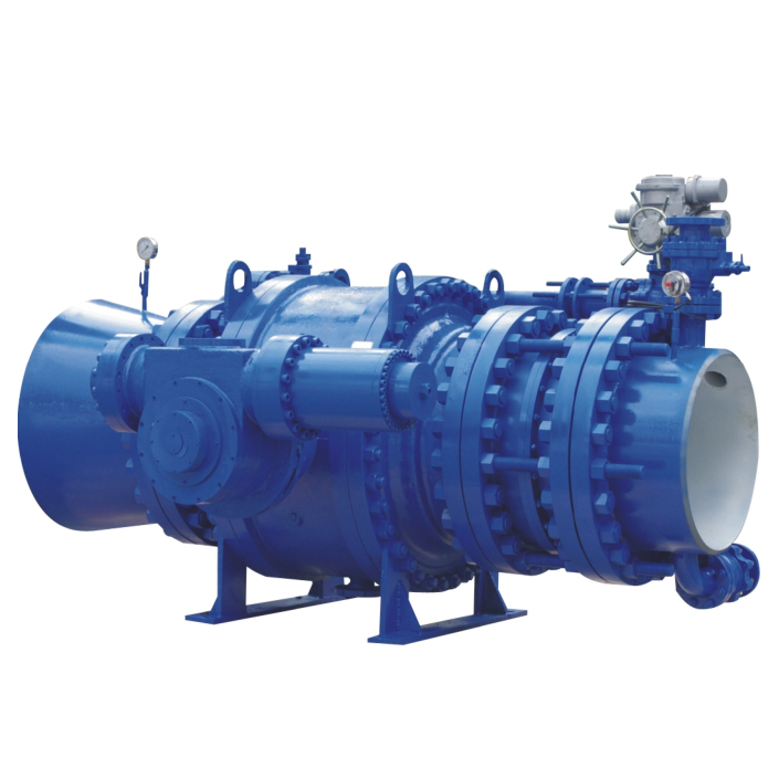
ZQ741F Hydraulic Ball Valve for Turbine and Pump Isolation
These hydraulic ball-valve assemblies are used for turbine-inlet isolation and pump or water-system shut-off duties. An accumulator or counterweight supplies stored energy for the chosen closing action, while the hydraulic control sequence determines closing speed and changeover. Select the required power-loss response together with the pipeline’s transient conditions.
Gas-charged accumulators store closing energy through compressed gas acting on hydraulic fluid; counterweight units use gravitational potential energy. The hydraulic circuit, valve load and control sequence determine the response to loss of power or pressure. Full-open and full-closed locking, PLC interlocks and manual-pump operation are selected with the supplied assembly.
Product Features
1. Control arrangement: local operation and remote PLC or DCS interfaces can be combined with pump, turbine and bypass-valve interlocks. Specify which signals permit opening and initiate closure, and how power loss changes the sequence. If a manual pump is included, its operating procedure must account for the circuit and valve load. Fast and slow stages and their changeover position are selected from the pipeline transient analysis; two stages alone do not guarantee elimination of water hammer.
2. Seat construction: one design option uses a PTFE sealing ring supported by a metal seat and spring preload. Its pressure, temperature and wear limits depend on the actual seat assembly. Spring loading can maintain contact within its designed travel, but does not make a worn or damaged seal indefinitely serviceable.
3. Fire-related sealing: some seat designs include a secondary metal-contact arrangement intended to limit leakage if a polymer seal is damaged by heat. Whether this feature is present and what fire-test qualification applies must be specified for the actual construction; the hydraulic drive alone does not establish fire performance.
4. Cavity pressure: a self-relieving seat arrangement can allow cavity pressure to discharge toward a selected side when the designed seat differential is reached. Other seat arrangements behave differently. Select the relief direction and system protection with the actual seat design rather than assuming that every valve cavity automatically relieves.
5. Drain, vent and auxiliary sealing connections: their functions depend on the supplied body and seat arrangement. A full-open or full-closed indication does not establish that the cavity and stem-seal area are safe to open. Before replacing packing or opening a connection, isolate and depressurize the process and control hydraulic, accumulator and counterweight energy according to the equipment-specific procedure. Do not loosen packing or cavity connections during operation.
6. Counterweight locking: where a mechanical or hydraulic locking arrangement is provided, use it according to the equipment procedure to control unintended movement. A position indication alone does not physically secure the counterweight.
7. Hydraulic pressure holding: the circuit and its valves determine how pressure is retained and how the assembly responds to internal leakage or pressure loss. Pressure-holding performance should be considered together with the required closing action, rather than described as universally leak-free.
8. Pressure-holding and compensation can use position or pressure signals. The controlled ball valve’s response to hydraulic-pressure loss is determined by the actual hydraulic circuit and closing-energy arrangement.
9. PLC integration: selected command, permissive and position signals allow the valve sequence to be coordinated with the plant controls. The required actions during power loss and restart should be defined along with normal operation.
10. Typical applications include turbine-inlet and pump-system isolation. Material, pressure-temperature conditions, hydraulic load and closing sequence determine the suitability of the complete assembly for each pipeline.
Frequently asked questions
Is accumulator closure the same as counterweight closure?
No. A gas-charged accumulator stores energy in compressed gas acting through hydraulic fluid; a counterweight uses gravitational potential energy. The required closing action depends on the selected circuit and mechanical arrangement.
Will two-stage closure eliminate water hammer?
It cannot be assumed to do so. Stage timing and changeover position must suit the pipeline and pump or turbine transient response. A fixed fast/slow sequence that suits one installation can be unsuitable for another.
Can maintenance rely on the valve being closed?
No. The process must be isolated and depressurized, and hydraulic pressure, accumulator energy and counterweight movement must be controlled before work on packing or cavity connections. Closed-position feedback alone is not maintenance isolation.
 Home
 Valve selection
 news information
 Contact us