


 简体中文
 Japanese
 Korean
 Russian
 繁体中文
 Español
Valve selection

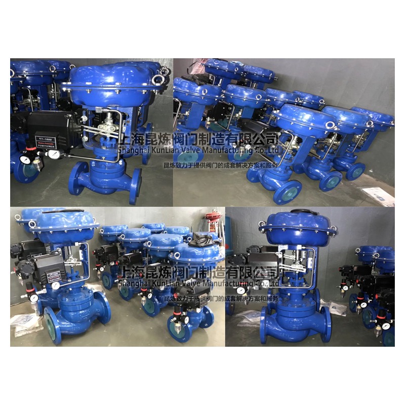
Pneumatic fluoropolymer-lined regulating valve HPF-16C
The HPF-16C pneumatic fluoropolymer-lined regulating valve adopts a straight through single seat structure, optional PTFE (F4), FEP (F46) or PFA lining, and pneumatic thin film actuator. It changes the flow cross-section through the linear displacement of the valve core and is used for flow regulation of corrosive medium pipelines. The product adopts flange connection, and the nominal diameter series is DN15–DN300.
PN16/PN25 in the pressure field describes series options, not two simultaneous ratings for one valve. Confirm the diameter and pressure configuration against the corresponding data sheet and nameplate. Nominal pressure does not establish the maximum allowable shut-off differential pressure, which must also match the trim, actuator and air supply.
The key to selecting this valve is to consider both the anti-corrosion structure and the regulating conditions: the selected fluoropolymer lining is responsible for liquid isolation, the single seat valve core and valve seat form throttling and closing parts, and the pneumatic diaphragm actuator provides the thrust required for valve stem movement. The compatibility of the medium, flow rate, pressure before and after the valve, and output of the actuator need to be matched with each other.
HPF-16C's straight through single seat structure
The straight through single seat structure is equipped with a set of main valve core and valve seat matching parts. The actuator drives the valve stem and valve core to rise and fall, changing the flow area between the valve core and valve seat; The medium flow rate varies with the valve opening and working pressure difference.
The metal shell bears the structural load, and the selected fluoropolymer lining inside the valve body separates the process medium from the corresponding metal substrate. The integrity of the valve seat contact area, valve stem sealing area, and lining end face respectively affect the closing seal, external seal, and corrosion resistance.
The single seat structure will generate unbalanced force on the valve core under the action of closing pressure difference. The selection of thrust for the actuator needs to take into account the pressure difference, sealing contact, and valve stem friction, and cannot be based solely on the valve diameter to select the same specification of actuator.
PTFE, FEP and PFA lining selection
HPF-16C is available with PTFE (F4), FEP (F46) or PFA lining. These are different fluoropolymers. State the selected lining material in the order and spare-parts records; their temperature, pressure and medium compatibility limits are not interchangeable.
The selection of corrosive media requires providing the name, composition, concentration, and operating temperature of the medium, as well as indicating whether it contains particles, whether crystallization occurs, and whether there is negative pressure or frequent changes in temperature. The chemical resistance of materials does not replace the structural applicability of the lining under pressure difference, erosion, and thermal cycling conditions.
The working temperature and pressure of valves are jointly limited by the pressure bearing shell, lining, valve internals, and seals. The material properties of fluoropolymer raw materials cannot be directly used as the rated value for the entire valve operation; When corrosive liquids vaporize or particles wash away at the throttling area, the impact on the lining and valve seat should also be evaluated.
The material names and application differences of different fluoroplastics can be readPFA, FEP, and PTFE lining material selection instructions。
Pneumatic thin film actuator and valve position control
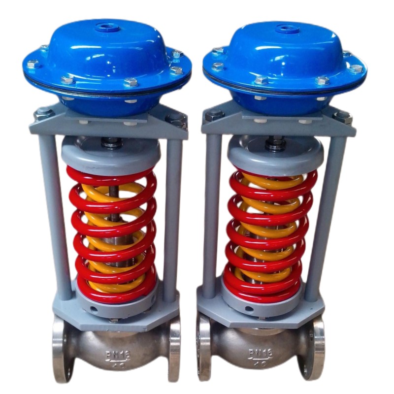
The pneumatic diaphragm actuator converts the air pressure acting on the diaphragm into linear thrust, which is then transmitted to the valve stem through connecting components. The gas supply pressure, spring working range, required stroke, and output thrust are different parameters that need to be matched with the actual closing pressure difference and adjustment stroke of the valve.
When configuring a valve positioner, the positioner adjusts the actuator air pressure based on input signals and valve position feedback to make the valve stem follow the target position. The input signal belongs to the control interface, and the compressed air belongs to the driving energy source. The two cannot be mixed and written as the same parameter.
The form of gas opening and closing, as well as the valve position after gas loss, are determined by the action mode of the actuator, the configuration of the spring, and the combination of valve components. The pipeline that needs to be closed or opened due to gas loss should have the required safe position written into the ordering conditions, and the actual action should be verified during debugging.
Product structural parameters and installation selection
| project | Structure and Configuration |
|---|---|
| Product Model | HPF-16C |
| Nominal diameter series | DN15–DN300 |
| Valve body flow channel | Direct single seat structure |
| connection method | flange connection |
| Lining material | PTFE (F4), FEP (F46) or PFA, selectable |
| Drive Type | Pneumatic thin film actuator |
| Valve core movement | Straight stroke lifting and lowering, changing the flow area between the valve core and the valve seat |
| main purpose | Flow regulation of corrosive medium pipelines |
When determining the flow capacity of a valve, it is necessary to provide the minimum, normal, and maximum flow rates, as well as the corresponding pre valve pressure, post valve pressure, temperature, and medium status. The nominal diameter represents the connection size and cannot alone prove that the valve has appropriate adjustment capability at all operating points. Other adjustment structures can be usedIndustrial Control Valve Selection ColumnChinese control.
- Before installation, clean the welding slag, impurities, and foreign objects inside the pipeline, inspect the lining end face and valve chamber, and do not use sharp tools to scratch the lining layer.
- Connect the pipeline according to the flow direction identification of the valve body, check the flange size, sealing surface, and structural length, and avoid forcibly pulling the pipeline with the valve.
- To reserve space for the actuator, valve stem connecting components, and subsequent disassembly and assembly, the arrangement of the air pipe should be easy to inspect and not hinder the movement of the valve stem.
- Check the air circuit connection, full stroke action, locator feedback, and required air loss position before putting it into use; The sealing test and action inspection are conducted separately.
- Isolate the process medium and driving gas source before maintenance, relieve pressure, and clean up residual medium. Do not disassemble the valve under pressure, and do not directly disassemble the actuator with stored spring force.
When inquiring, provide the medium, concentration, temperature, flow rate at each operating point, pressure before and after the valve, connection requirements, gas source conditions, and control methods to Fouten Flow Control (Jiangsu) Co., Ltd., which can be used to determine the matching scheme for lining, valve internals, and pneumatic actuators.
HPF-16C Pneumatic fluoropolymer-lined Control Valve Common Problems
Which linings are available for HPF-16C?
PTFE (F4), FEP (F46) and PFA linings are available. Specify the actual lining in selection, ordering and spare-parts records, and confirm the service limits for the selected material separately.
What parameters should be considered when selecting pneumatic thin film actuators?
It is necessary to verify the available gas source, the working range of the actuator spring, the effective stroke, and the output thrust, and determine the combination based on the maximum closing pressure difference of the valve, valve stem friction, and the required loss of air position. When using a locator, it is also necessary to match the input signal with the valve position feedback.
Can the diameter of HPF-16C be directly selected according to the diameter of the pipeline?
We cannot just look at the diameter of the pipeline. The required flow capacity and operating opening should be calculated based on the minimum, normal, and maximum flow rates, as well as the pressure difference at each operating point. For media that are prone to vaporization, contain particles, or are prone to crystallization, it is also necessary to check the impact of the throttling process on the lining, valve core, and valve seat.
 Home
 Valve selection
 news information
 Contact us