


 简体中文
 Japanese
 Korean
 Russian
 繁体中文
 Español
Valve selection
Why is it possible for the valve chamber to increase pressure after the pneumatic ball valve is closed? Liquid trapped pressure and pressure relief path
If liquid is trapped in the closed ball valve chamber, an increase in temperature may cause a change in chamber pressure. The customer needs to provide the medium, temperature rise and isolation status, confirm the actual structure and pressure management, and cannot change the valve seat pressure relief path on their own.
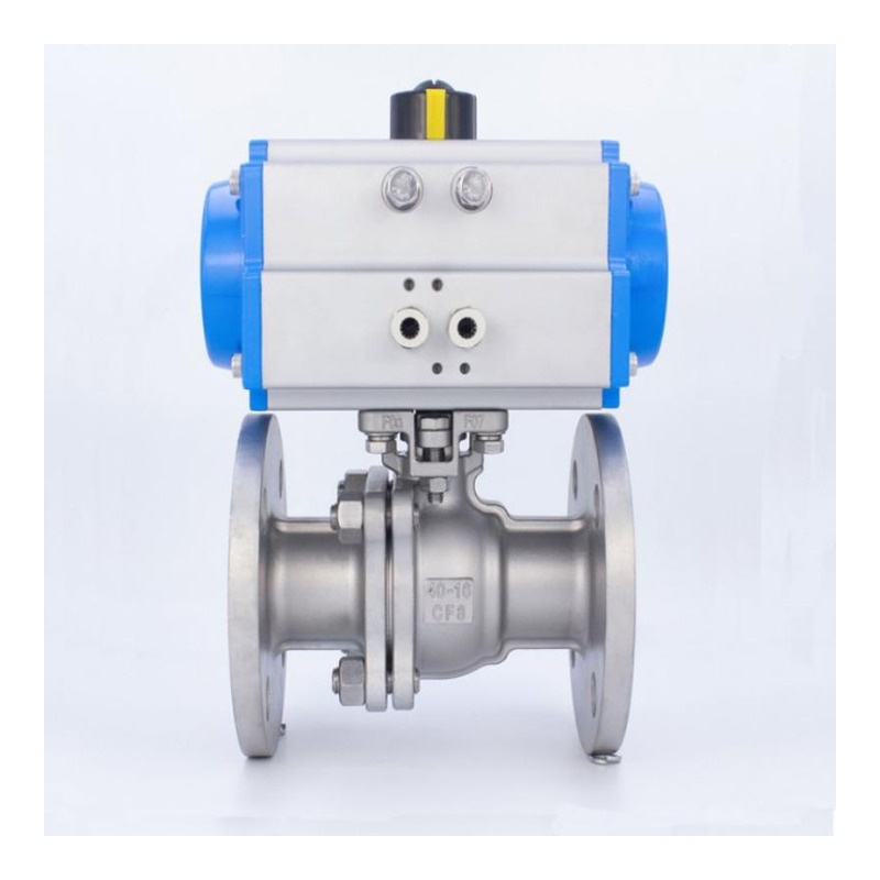
Valve chamber pressure and pipeline pressure are not the same measuring point
The main channel of the ball valve and the internal clearance of the valve body have different geometric positions. After closure, the valve seats on both sides, the spherical holes, and the valve body structure jointly determine which spaces are enclosed and which spaces still have connected paths. The normal reading of the pressure gauge upstream or downstream of the pipeline cannot alone prove that there is no residual liquid or pressure in the valve chamber. Whether there is trapped pressure should be judged based on the actual structure and operating status.
The processes that need to be emphasized include temperature rise after shutdown, heat tracing changes, hot cleaning, and external thermal conditions such as sun exposure. The occurrence of a temperature difference does not necessarily mean dangerous pressure rise, but when the liquid is restricted, temperature changes, and the lack of an effective release path coexist, the closed state cannot be simply equated with an energy free state.
Pressure rating cannot replace valve chamber overpressure assessment
The rated pressure of the valve body is used for pressure evaluation under corresponding material and temperature conditions, and cannot be used as a reason for infinite increase in trapped pressure. The valve seat, valve stem seal, and valve body connection also have load boundaries. Only replacing the ordinary ball valve with a higher PN, without specifying where the pressure is released after the liquid expands, and whether the release process meets the process requirements.
When purchasing, the medium, temperature at shutdown, possible temperature, heat tracing or cleaning process, and the status of upstream and downstream during shutdown should be provided. The manufacturer confirms the function of the valve chamber and valve seat based on this, and re evaluates the system design to determine whether corresponding overpressure management is needed. We cannot simply delete this requirement based on low work pressure.
The self relief valve seat, connecting structure, and external protection should be confirmed separately
Some ball valves adopt a valve seat structure that can release the pressure in the valve chamber, while others are designed to manage trapped pressure through specified internal communication paths and may also require system level protection. Different schemes have different directions of action, opening conditions, and applicable media. If the words "floating ball" or "fixed ball" cannot be seen, it is assumed that the entire valve has the same pressure relief capacity.
The pressure relief path and isolation task should also be compatible. If the pressure in the valve chamber is released to a certain pipeline side, it must be clarified whether that side can accept it in the most unfavorable state and whether it affects bidirectional isolation or other functions. Technical confirmation should include structural description and corresponding verification, and the presence of external joints should not be used as proof of automatic pressure relief, let alone on-site processing of through holes to change the finished product.
Pneumatic fault location solves another problem
Describe the state of the valve when the valve is in the closed, open, or held position due to a malfunction; Valve chamber pressure management describes the direction of trapped media inside. After choosing to close the valve due to gas loss, the valve may remain in the closed state for a longer period of time, so it is still necessary to check the temperature changes during the shutdown period. The two requirements should be listed separately, and the fault safety position should not be used as a substitute for valve chamber evaluation.
The Q641F-16C page of Fouten introduces the pneumatic floating ball structure, which can be used to verify valve identity and drive configuration. The valve chamber release function is a finished product structure that requires separate confirmation and is not directly proven by the Q641F model, cylinder size, or switch in place feedback. When inquiring, please list this requirement separately to facilitate the manufacturer's explanation of the actual valve seat and medium conditions.
Maintenance cannot only focus on the pressure gauges on both sides
The internal residual and pressure state after the valve is closed is the boundary that needs to be identified for isolation and maintenance plans. When involving hot liquids, hazardous media, or heat tracing pipelines, the operation should follow approved isolation, temperature, and residual energy confirmation procedures. Loosening bolts, forcibly rotating or temporarily dismantling joints should not be used as a method to test the pressure in the valve chamber.
Valve chamber working condition confirmation form
| Information | Corresponding issues |
|---|---|
| Media and residues | Which spaces may retain liquid after closure |
| Temperature process | Heat tracing, cleaning, shutdown, and external heating |
| Valve seat and connection | Release direction, action conditions, and structural evidence |
| Isolation requirements | Does the release path comply with system functionality |
| Fault status | Residence time and temperature changes after gas loss |
Corresponding products and further selection
The safety boundary after the ball valve is closed not only depends on whether it is cut off at both ends, but also on the temperature and pressure changes of the residual medium inside. By verifying the operation process, valve seat action, and release path, it is more targeted than simply requiring a higher pressure rating.
Can be combinedPneumatic flange ball valve Q641F-16CThe actual product information confirms the structure and selection requirements. For more similar products, please refer toPneumatic Valve Column。
General principle reference:Relia Valve Chamber Release Structure Description;Emerson KTM E01 Structure DescriptionThe specific functions of the finished product are based on the corresponding structure and verification data.
Common customer questions
Both upstream and downstream pressure gauges are normal, do we still need to confirm the valve chamber?
Need. The pressure gauge measures the corresponding pipeline side, whether the valve chamber is connected and whether there is trapped liquid, which should be checked according to the valve seat and internal structure.
If we replace it with a fixed ball valve, will there be automatic valve chamber pressure relief?
It cannot be judged solely based on the spherical support form. Different valve seats have different functions, and the release direction, conditions, and verification data of the finished product need to be confirmed.
Can the pneumatic ball valve be opened when it loses air, thus eliminating the need for pressure testing?
No. Still need to consider normal shutdown, other faults, and shutdown status; The fault action and valve chamber pressure management should be evaluated separately.
 Home
 Valve selection
 news information
 Contact us