


 简体中文
 Japanese
 Korean
 Russian
 繁体中文
 Español
Valve selection
What is the difference between regulating valve flow opening and closing and air opening and air closing? Do not mix flow direction and drive
Flow opening and flow closing refer to the influence of flow on the internal components of the valve, while air opening and air closing refer to the relationship between driving and action. Only by confirming the four words separately can the flow direction, normal control, and fault location be written correctly.
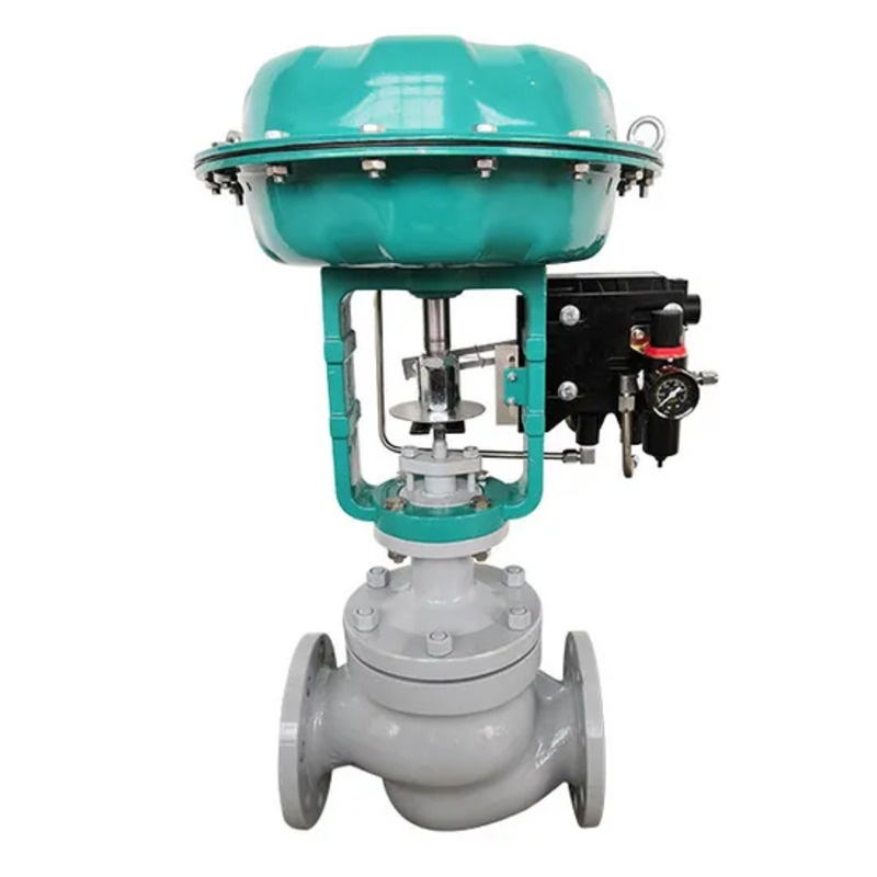
Flow opening and flow closing describe how fluid acts on opening and closing components
For the corresponding valve structure, fluid forces may tend to assist in opening or closing, so descriptions such as flow opening or flow closing are used. The direction of action is related to the geometric shape of the valve internals, actual flow direction, and pressure conditions, and cannot be judged solely based on the shape of the straight through valve body. Different structures or even the same series of different internal components require corresponding flow data.
The tendency of the fluid to close does not necessarily mean that the valve can reliably shut off under all pressure differentials; The tendency of the fluid to open does not mean that the actuator cannot be closed. The actual load also needs to take into account other forces and institutional capabilities. These terms are used to understand and verify the structure, and do not replace the calculation of closing pressure difference, driving force, and finished product function.
Air opening and closing describe the motion relationship driven by air pressure
For the corresponding pneumatic configuration, increasing the applied air pressure to move the valve in the opening direction can be called pneumatic opening; Increasing the applied air pressure causes the valve to move towards the closing direction, which can be called gas closing. It should be confirmed whether what is described here is the function of the actuator, the output of the valve positioner, or the mapping of control signals in the system, and not to mix the "positive and negative effects" of different levels in one column.
The target valve position after the control system signal increases is also affected by the valve positioner and control configuration. The pneumatic mechanism, valve positioner input and output, and control direction of DCS should be checked together. Only changing the display direction on the screen does not alter the actual spring or fluid action, and cannot replace the complete set of tests.
The flow direction and location of gas loss need to be independently specified
After losing effective air pressure, the single acting spring mechanism may tend towards the corresponding position according to the actual configuration, but the final action still depends on the load and system status. Double acting mechanisms have different gas path conditions. It is not enough to omit the verification of actuators, valve positioners, and loss of air status based solely on one word: air open, air closed, or flow open, flow closed.
Power loss and gas loss may not necessarily trigger the same process. The project should clarify what faults need to be addressed and how to take action, and then implement them through a complete set of configurations. The installation flow direction is confirmed based on the actual finished product arrows and drawings; The valve body cannot be installed in reverse on the pipeline without the design's consent in order to obtain the desired fault location.
These pieces of information will affect stability and load shedding
The effect of the medium on the opening and closing components may vary with pressure difference and opening degree. The flow direction selection, valve internals, and driving capability jointly affect the response and shut-off, and cannot be replaced by a fixed "more labor-saving" judgment for design. High pressure difference, gas, two-phase or abnormal flow processes also require corresponding operating condition evaluations, without directly applying conclusions from another medium.
The ZJHP-16C pneumatic single seat regulating valve of Fouten adopts a straight stroke valve stem and a thin film pneumatic actuator. The safety positions of air opening, air closing, and gas loss are confirmed according to the project configuration. The single seat name does not specify a unique installation flow direction or control for positive and negative effects. The arrows, structure, and driving data of this finished product should be consistent and cannot be replaced by a universal model table.
Verify at least three directions and one status during delivery
Purchase confirmation shall specify the specified flow direction of the medium, the direction of gas supply, the corresponding valve position of the control signal, and the final state in case of agreed failure. Please provide a complete set of structure and control instructions, recording the normal and maximum closing pressure difference, effective gas source, and feedback requirements. This is not only convenient for suppliers to configure, but also for debugging personnel to distinguish between structural direction and signal direction.
Acceptance checks the correspondence between commands, valve stem movement, and feedback under approved conditions, and verifies the required fault actions according to specialized procedures. When the direction is found to be inconsistent, first check the file against the actual configuration, and do not attempt to connect the pipeline in reverse, change the gas path arbitrarily, or shield the interlock. After replacing the valve positioner or actuator, the corresponding relationship should also be reconfirmed.
Four Directions and Status Checklist
| Terminology or information | Verify the object |
|---|---|
| Flow open or flow closed | Fluid action and real valve internal structure |
| Air open or air closed | Action pressure and actuator movement |
| Signal positive and negative effects | Input commands, valve positioners, and target valve positions |
| Regulate the flow direction | Finished product arrows, drawings, and pipeline connections |
| Fault location | Fault events, available energy, and complete validation |
Corresponding products and further selection
Flow term should help to clarify the true force, rather than replace product configuration. Separating the fluid action, air pressure action, signal mapping, and fault status can reduce directional disputes during installation and commissioning, and also reserve accurate basis for subsequent spare parts replacement.
Can be combinedPneumatic single seat regulating valve ZJHP-16CThe actual product information confirms the structure and selection requirements. For more similar products, please refer toRegulating valve column。
Related questions can continue to be read:What is the difference between pneumatic valve loss of air and power? Guidelines for Fault Safe Location and Interlock Configuration。
General principle reference:Explanation of Flow Direction and Opening/Closing Function of NTGD Globe ValveThe specific functions of the finished product are based on the corresponding structure and verification data.
Common customer questions
Does the gas regulating valve always allow the medium to enter below the valve seat?
It cannot be inferred in this way. The air opening describes the action and movement of air pressure, and the specified flow direction needs to be confirmed according to the specific valve components, arrows, and finished product drawings.
Can the valve body be reversed to change the gas opening to gas closing?
No. The flow direction of the pipeline and the function of the actuator are different conditions, and the control function should not be changed through unconfirmed reverse installation.
Will the position of the lost air also change if the display direction of DCS is changed?
It will not change the mechanical action solely due to display changes. The spring, air circuit, valve positioner, and load conditions need to be confirmed separately according to the actual configuration.
 Home
 Valve selection
 news information
 Contact us