


 简体中文
 Japanese
 Korean
 Russian
 繁体中文
 Español
Choose pneumatic or electric control valve actuation by the available energy supply, required modulation and the valve position needed after a failure. Reliable instrument air makes pneumatic actuation worth evaluating; where air is impractical, assess an electric package. Neither choice automatically guarantees speed, accuracy or a safe failure position.
Start with the control valve selection guide for medium, valve construction and capacity. This guide compares actuation packages without assigning one response time, signal or failure action to every product.
What is the main difference?
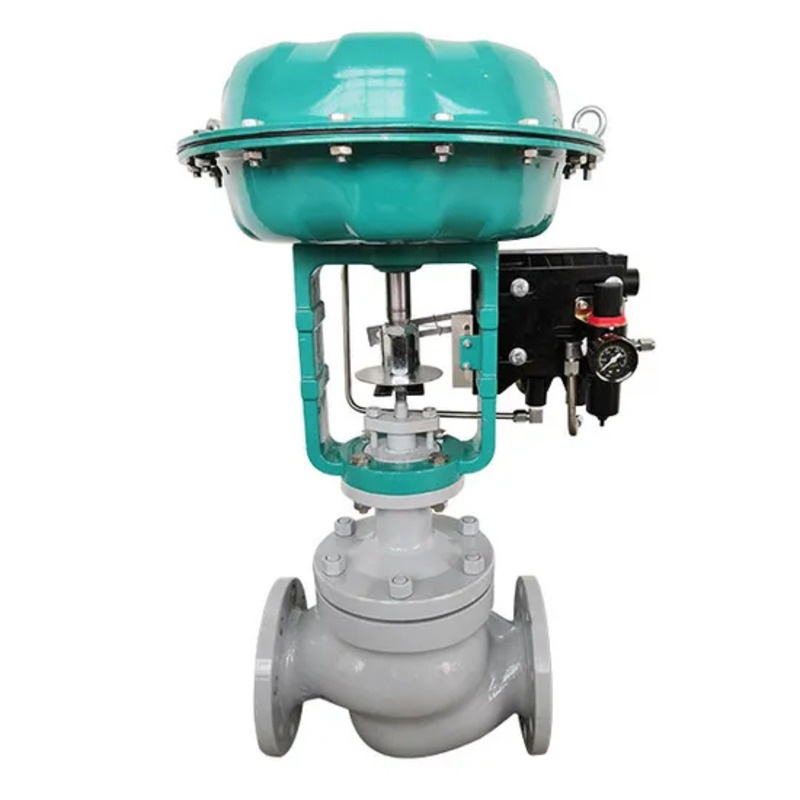
A pneumatic actuator uses compressed air to move a diaphragm or piston. A modulating assembly can use a positioner for valve-position feedback and signal following. An electric actuator uses a motor and transmission; continuous modulation and available interfaces depend on the actuator and control module.
Single-seated, cage-style and V-port refer to valve or trim construction; pneumatic and electric refer to actuation. Select an appropriate throttling arrangement and then match the drive. See single-seated versus cage-guided control valves before treating actuator replacement as a change in flow performance.
Site selection comparison
On a phone, scroll the table horizontally to read the complete requirements.
| Procurement check | Pneumatic package | Electric package |
|---|---|---|
| Energy supply | Available air pressure, capacity, cleanliness and line losses | Main supply voltage, AC/DC, power availability and wiring |
| Control and feedback | Positioner/accessory input, feedback and communication options | Control-module input, feedback and communication options |
| Output capability | Match actual air supply, spring arrangement, travel and valve load | Match output thrust/torque, travel, duty rating and valve load |
| Response and frequency | Assess the assembled air circuit, positioner and actuator under load | Check modulation frequency, permitted starts, thermal load and travel time |
| Failure position | Check springs, air circuit and accessories; distinguish air loss from power loss | Confirm holding or stored-energy/return options; do not assume automatic closure |
| Maintenance | Air treatment, leaks, tubing and positioner service | Wiring, control module, transmission and environmental protection |
Why is full-stroke time not the complete response specification?
Continuous control also depends on small-signal movement, deadband, hysteresis and travel following under the actual differential pressure. Test pneumatic assemblies with their air supply and positioner. For electric assemblies, check modulation duty, heat from frequent operation and feedback settings.
Specify load changes, operating frequency and permitted response time so proposals use comparable conditions. An unloaded actuator speed is not a complete valve response guarantee, and valve-position accuracy is not the same as flow or temperature control accuracy.
Specify air loss, power loss and signal loss separately
Loss of instrument air, loss of power to a positioner or solenoid, and loss of the control input are different events. Spring arrangements, actuator/valve action and the accessory circuit determine the resulting pneumatic valve position. A double-acting actuator should not be assumed to hold position without checking its circuit.
An electric actuator may stop when power fails, or a specific spring or stored-energy design may perform a defined action. Confirm the actual package. A 4–20 mA interface, fieldbus or an intelligent label does not establish a fail-safe function. The air-loss and power-loss guide explains the distinction in more detail.
Size the valve and closing load before choosing the actuator
Minimum, normal and maximum flow determine the needed capacity and travel range. Shut-off differential pressure, trim forces and sealing requirements contribute to actuator loading. Do not size either actuator simply by nominal pipe diameter. Review Cv, Kv and flow characteristics for the capacity checks.
Liquid, gas and steam duties have different sizing and risk checks. High pressure drop, noise, cavitation or flashing require suitable trim and system evaluation; changing the drive is not a universal solution.
Information to include in a quotation request
- Medium and phase, temperature, minimum/normal/maximum flow, upstream/downstream pressures and shut-off differential pressure.
- Body/trim materials, DN, connections, leakage acceptance and proposed valve construction.
- Instrument-air conditions, or supply voltage, frequency, phases and electrical constraints.
- Control input, valve-position feedback, communications, local/remote permissions and accessory scope.
- Required positions after air, power and signal failure, plus response, operating frequency, enclosure/hazardous-area and maintenance requirements.
Compare the actual ZJHP-16C pneumatic single-seated control valve and ZDLP-16C electric single-seated control valve data. They are representative products, not direct substitutes under every trim, pressure-temperature or interface configuration. See electric control valve input and feedback configuration for interface checks.
Technical references and limits
General actuation and position-following principles are described in Spirax Sarco's actuator and positioner guide and the Emerson Control Valve Handbook. These explain engineering principles; they do not establish Fouten ratings or certifications. The quotation and acceptance must identify the actual valve, actuator and accessories.
 Home
 Valve selection
 news information
 Contact us